solid state relay

如何连接固态继电器

固态继电器 (SSR) 是一种安静、快速且可靠的使用低压信号切换高压设备的方法。无论您是自动化加热器、使用 Arduino 控制灯,还是构建工业面板,本指南都将引导您清晰、自信地了解您需要了解的所有内容。

什么是固态继电器,它是如何工作的?

Solid State Relay vs Mechanical Relay: What’s the Difference?

机械继电器的工作原理类似于微小的金属开关。当电磁线圈拉动内部触点时,它们会发出咔嗒声打开和关闭。但随着时间的推移,机械部件会磨损、产生噪音并变得不那么可靠。

相比之下固态继电器没有移动部件。他们使用双向可控硅开关或晶体管等半导体来进行开关。没有咔嗒声,没有弧线,没有弹跳。这意味着更长的使用寿命、更快的开关和更安静的运行。

SSR 的基本组件和内部工作原理

在 SSR 内部,有两个关键方面:输入和输出。当控制信号发送到输入侧(通常是低压直流电)时,它会激活光耦合器。这可以安全地触发输出侧的开关元件,例如双向可控硅开关或 MOSFET。

由于控制侧和输出侧是光学隔离的,因此即使在切换高压负载时,低压设备(如 Arduino)也能保持安全。这就是 SSR 在敏感电子系统中如此受欢迎的原因之一。

固态继电器的常见用例

您会在各种地方找到 SSR:工业自动化、3D 打印机、HVAC 系统、家用电器。它们非常适合开关灯、风扇、加热器和电机。制造商经常使用它们让微控制器安全地控制高压交流设备。

Solid State Relay

了解固态继电器的端子

现在您已经了解了 SSR 的工作原理,让我们动手实践一下。了解电线的连接位置对于避免混乱和损坏至关重要。

Input Side (Control Terminals and Trigger Voltage)

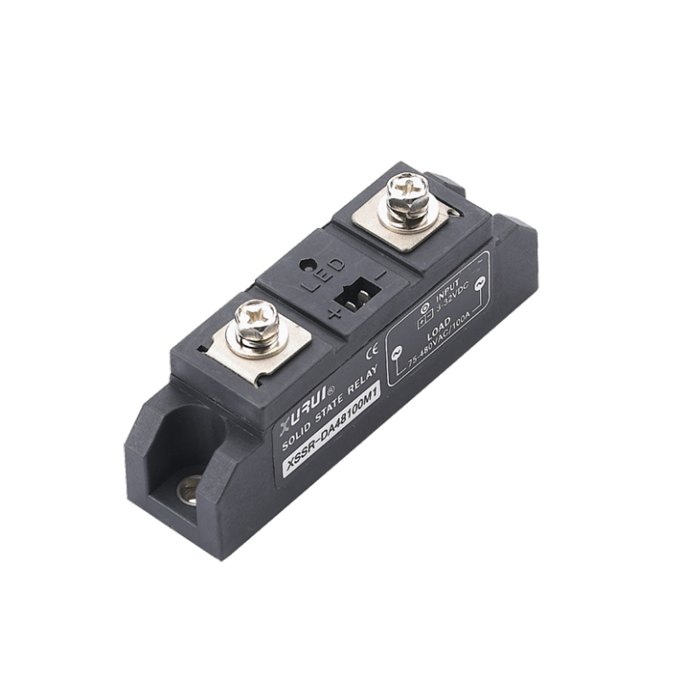
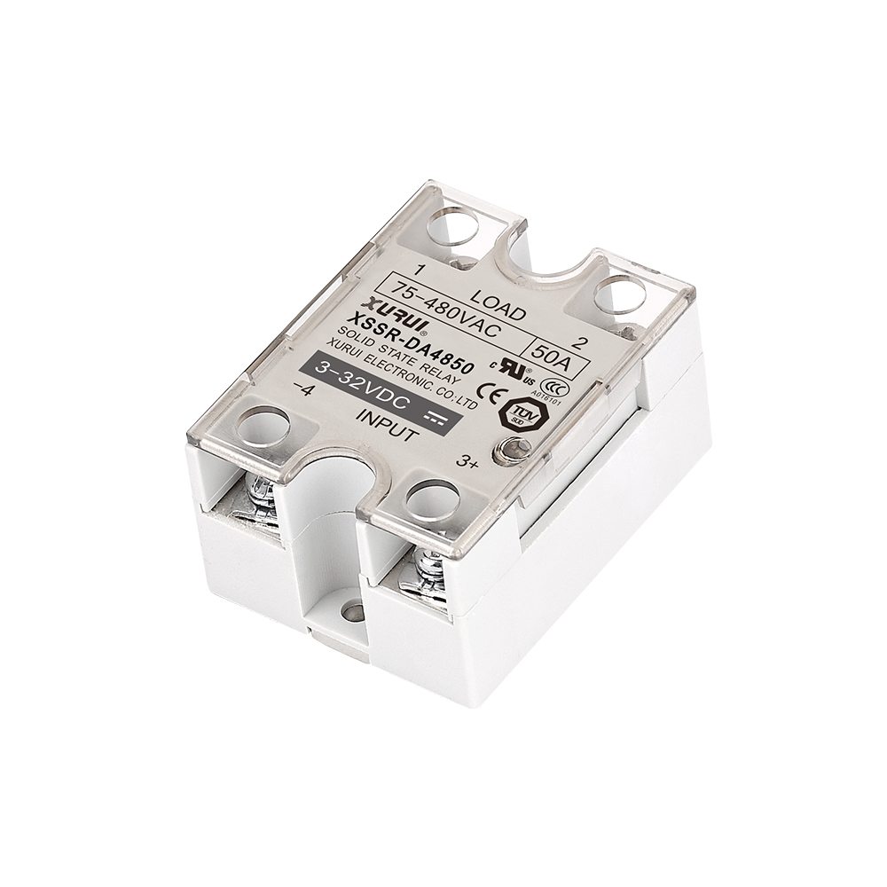
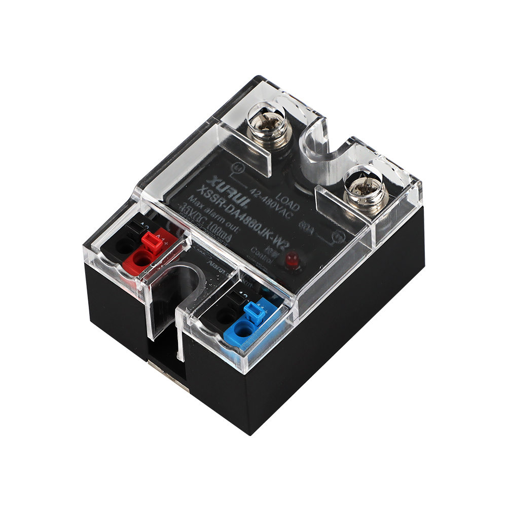
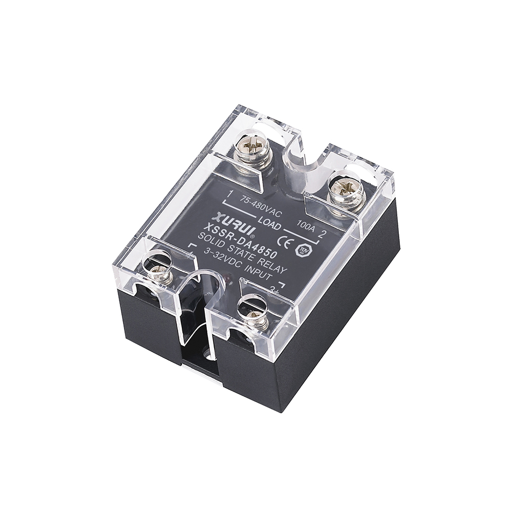
输入侧(通常标记为“+”和“−”或 3 和 4)接收控制信号。它可以是来自 Arduino 的 5V 信号或来自 PLC 的 24V 信号。请务必检查继电器的输入电压范围。如果不匹配,SSR 根本无法打开。

输出侧(负载端子和开关电路)

The output side—commonly marked 1 and 2—is where the power flows to your load. This is where you switch your AC or DC load on or off. For DC loads, pay attention to polarity. For AC loads, polarity usually isn’t an issue.

解释端子标签和极性

每个 SSR 都有标签,但并非每个标签都是相同的。有些使用数字,有些使用符号。关键是知道哪一侧控制电路,哪一侧承载负载。如有疑问,请阅读数据表。

选择正确类型的固态继电器

Before you start wiring, you need to make sure you’ve got the right type of SSR for your project. Let’s break it down.

AC-AC、DC-AC、DC-DC – 您需要哪一个?

将您的 SSR 与您正在使用的信号类型和您要切换的负载相匹配。如果您使用直流控制信号来切换交流负载(非常常见),请选择 DC-AC SSR。对于 DC-DC 或 AC-to-AC 需求,请相应选择。

根据负载类型选择SSR(电阻与电感)

加热器和灯是电阻负载。电机和电磁阀是电感式的。电感负载需要格外小心,例如缓冲电路或反激式二极管,以保护 SSR 免受电压尖峰的影响。

需要考虑的关键规格:电压、电流、触发范围

检查三个关键规格:输入电压(您的控制器可以驱动它吗?)、输出电压/电流(它可以处理您的负载吗?)和开关类型(某些 SSR 在交流交零点时切换)。

相关阅读: 固态继电器适合您吗?

如何逐步连接固态继电器

你的继电器被选中了吗?太好了,让我们连接起来吧。慢慢来,仔细检查一切,你会没事的。

您需要的工具、电源和接线材料

您需要 SSR、螺丝刀、适当规格的电线、万用表,也许还需要散热器或缓冲器。使用交流电路时,安全手套是一个加分项。

如何安全地连接控制侧(Arduino、PLC 等)

Connect your low-voltage control signal to the SSR’s input terminals: digital pin or control output to “+”, ground to “−”. If your controller doesn’t provide enough voltage, use a transistor or driver.

How to Wire the Load Side to an AC or DC Device

将负载与 SSR 的输出串联。例如:交流火线连接到 SSR 端子 1,端子 2 连接到您的灯,然后回到中性线。对于直流电,连接正确的极性。切勿像开关一样在两个 SSR 端子上连接负载。

为电路供电前的最终检查

确保没有松动。测量控制端子两端的电压。确认您的负载电流不超过 SSR 的额定值。然后打开电源并测试它。

Solid State Relay

常见场景的接线图示例

这里有一些实际示例,可帮助您了解这一切的实际效果。

将 SSR 连接到 Arduino 和交流灯

数字引脚到 SSR +,Arduino GND 到 SSR −。在输出侧,火线连接到端子 1,端子 2 连接到灯泡,然后连接到交流中性线。当 Arduino 输出高电平时,灯亮起。

使用带有SSR的PLC驱动直流电机

将 PLC 输出连接到 SSR 输入,电流/电压适当。输出端子与电机和直流电源串联。在电机上添加一个反激二极管以抑制尖峰。

用于控制加热器的手动开关和 SSR 设置

在电源和 SSR 输入之间连接手动开关。在负载侧,像使用普通开关一样通过 SSR 输出连接加热器。简单、安全、有效。

安全可靠 SSR作的技巧

一些小事对于使您的 SSR 设置持续时间更长、工作得更好大有帮助。

使用适当的电压和电流额定值以确保稳定性

选择额定值至少比预期负载高 20-30% 的 SSR。如果您的加热器消耗 8A,请选择 10A 或 15A SSR。这种开销可以防止热应激并延长使用寿命。
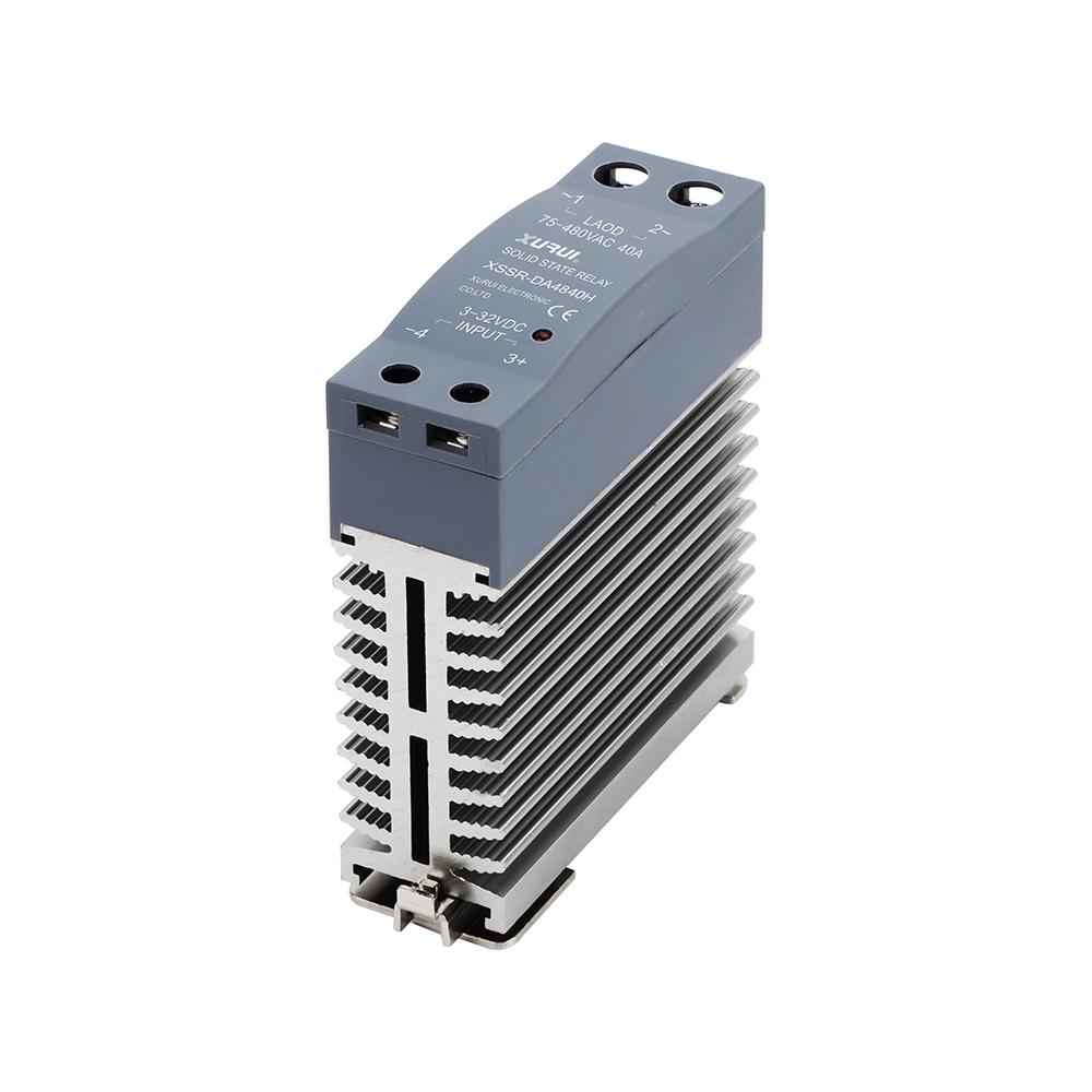
为高于 5A 的负载添加散热器

SSR 会变热,尤其是在连续负载的情况下。将继电器安装到金属面板上或使用专用散热器。遵循数据表的散热建议。

使用缓冲器或反激式二极管保护您的电路

缓冲器可帮助交流 SSR 在不产生电弧的情况下切换感性负载。对于直流,负载两端的反激式二极管可防止电压尖峰烧毁继电器。

使用实际负载进行测试——而不仅仅是万用表

SSR 通常需要实际电流才能正常运行。如果它没有发出咔嗒声或亮起,请不要认为它坏了。插上实物,在工况下观察。

连接 SSR 时要避免的常见错误

让我们避开这些初学者陷阱,为您省去一些挫败感。

混淆输入和输出端子

一侧是控制,另一侧是开关电源。翻转它们,什么也没用——或者更糟糕的是,有东西烧焦了。检查标签和图表。

使用过小的触发信号

3.3V 信号无法驱动 12V 额定 SSR。使用逻辑电平 SSR 或在控制和继电器之间添加晶体管开关。

忽略散热要求

没有散热器?期待失败。热失控是真实存在的。如果继电器摸起来很热,则需要冷却解决方案。

省略电路保护(保险丝、断路器等)

SSR 不能保护您的负载,而是您必须保护。安装与高压接线一致的保险丝或断路器。

故障排除:为什么我的 SSR 无法正常工作?

SSR给你带来麻烦?以下是诊断方法。

SSR 未打开 – 检查触发电压和极性

测量控制输入两端的电压。如果它在范围内但没有任何反应,请检查极性。直流输入关心哪一侧是 +,哪一侧是 −。

SSR Always On – 了解泄漏和负载类型

一些 SSR 即使在关闭时也会泄漏小电流。对于低功率负载,这可能足以让它们保持昏暗或旋转。添加一个泄放电阻器将其排出。

负载闪烁或意外关闭

您的连接可能不良或控制电压降。确保端子紧固且控制器输出稳定。

继电器过热或过早失效

电流被低估、没有散热器或通风不良?先解决这些问题。还要检查电机或变压器是否有电感尖峰。

相关阅读: 解决实际问题的 15 个固态继电器故障排除技巧

常见问题解答(FAQ)

Q1:我可以将固态继电器直接连接到 Arduino 或 Raspberry Pi 吗?
是的,只要 SSR 接受 3.3V 或 5V 输入。否则,请使用驱动器晶体管或光隔离模块。

Q2:我如何知道我的 SSR 是交流型还是直流型?
查找标签或数据表符号。正弦波表示交流电;直线或“+/-”表示直流。

Q3:SSR 需要散热器吗?
对于 5A 以上的任何东西,是的。否则,它们会过热并失效。

Q4:为什么我的SSR无法完全关闭?
漏电流或感性负载是常见原因。添加缓冲器或泄放电阻器。

Q5:SSR可以切换电机或风扇吗?
是的——如果它们的额定值是感性负载。请务必添加反激式二极管或缓冲器等保护。

结论

固态继电器提供了一种智能、高效和可靠的方法来使用低压逻辑控制高压电路。通过了解它们的工作原理、选择正确的类型并正确接线,您可以充分利用它们的速度、静音和耐用性。无论您是楼宇自动化面板的工程师还是尝试微控制器的业余爱好者,掌握 SSR 都会打开一个充满安全、强大开关可能性的世界。慢慢来,遵循最佳实践,您将立即充满信心地进行切换。

Difference Between Solid State Relay and Ordinary Relay

Difference Between Solid State Relay and Ordinary Relay

Relays are basic components used to switch electrical connections in the worlds of electronics and robotics, which are constantly evolving. Out of all the types that are out there, the most common ones are the solid state relay (SSR) and the ordinary electrical relay.  We’ll talk about the main differences between these two types of relays, as well as the best times to use each one.

Difference Between Solid State Relay and Ordinary Relay

The information in this part will help you learn how both types work.

Definition of Solid State Relay (SSR)

Electric circuits are controlled by semiconductors like thyristors, triacs, or MOSFETs in a solid state relay, which is an electronic switching device. SSRs differ from mechanical switches because they do n’t have any moving corridor. This makes switching quiet, keyless, and very reliable.

SSRs are often the best choice for tasks that require quick switching, noise reduction, and long-term durability.  These relays will be made by a famous solid state relay manufacturer to last millions of rounds without breaking.

Definition of Ordinary Relay (Electromechanical Relay)

When you use an electromagnet to move metal contacts on a regular or electromechanical relay (EMR), the circuit can be opened or closed.  People can fete these switches by the clicking sound they make. Because they’re cheap, they’re frequently used in artificial and ménage widgets.

EMRs, on the other hand, wear out over time because they move around, which limits their switching frequence and length of life compared to a solid state relay.

Core Working Principles Compared

At its core, the primary difference lies in how the breaker switches things on and off.  EMRs depend on mechanical stir to turn on a semiconductor switch, while solid state relays use electrical signals to do the same.

This difference has an immediate impact on performance, conservation, trustability, and the range of operations that can be employed. Working with a solid state relay manufacturer with a lot of experience will help you get exact performance specs that fit the requirements of your system.

solid state relay

Key Differences Between Solid State Relay and Ordinary Relay

That’s enough about the basics. Let’s look at the two types of relays side by side in terms of essential features that you’d use in real life.

Switching Mechanism: Contactless vs. Mechanical

Solid state relays use semiconductors to make switches, so they do not need to be physically touched to work.  This eliminates touch bounce and arcing, which are common issues with EMRs.  Normal relays, on the other hand, are physically open and close connections, which causes wear and tear and breakdown over time.

Because of this, SSRs are ideal for high- cycle operations where life is pivotal.

Performance and Durability

One great advantage of solid-state relays is that they have a long lifespan.  Because they don’t have any working parts, SSRs last a lot longer—under ideal conditions, they can last over 100 million rounds.  Most mechanical switches can only handle between 1 and 10 million turns.

Strong parts and heat management features will be used by a top solid state relay manufacturer to make performance and life expectancy even better.

Response Time and Switching Speed

Response time is better with SSRs than with EMRs.  Because they are mechanical, EMRs have pauses when they switch on and off, but solid state relays usually switch on and off within microseconds.  This is particularly important for robots, high-speed automation systems, and those that operate in tandem.

Electrical Noise and Vibration Resistance

Solid state switches do not make electrical sparks or pops because they do not make touch with anything. This makes them perfect for places that do not want noise and for systems that are prone to vibration.

Because they are mechanical, regular switches are more likely to chatter or fail in these kinds of conditions.

Size, Mounting, and Form Factor

SSRs usually come in smaller, more flexible forms.  Because they are smaller, they can be mounted in a variety of ways, such as on DIN rails or PCBs.  Because they have coils and touch arms, EMRs tend to be bigger.

A solid state relay is easier to fit into systems with limited room because it has a slim, basic design.

solid state relay

Application Scenarios and Industry Use Cases

It depends on the situation whether to use an SSR or an EMR.  This section provides detailed information about the environments where each type performs best.

Ideal Use Cases for Solid State Relays

This is what solid state switches are great for:

· Systems for automating factories

· Units for weather control and HVAC

· Equipment and gadgets for medical use

· Equipment for making food

· Control systems for lights

In these situations, the machines must be quiet, accurate, and durable. SSRs are great at all of these things.  For each of these areas, a solid state relay manufacturer you can trust will make models that are just right.

When Ordinary Relays Are More Suitable

Even so, regular runs might still be better when:

· Cost is a big worry.

· The frequency of switching is low.

· The load is only passive.

· There needs to be audible click input (for example, in-home tools).

EMRs might be enough in systems with low demand and few switching cycles because they are simple.

Industry Examples: From Automation to Consumer Electronics

Solid state switches offer the quick switching and responsibility needed for automatic product lines to reduce time-out. Normal relays, on the other hand, are constantly used in low- frequence systems, similar as washing machines, power sources, and alarm systems.

The important thing is to get the relay from a dependable solid state relay manufacturer and make sure it works well with your work and the surroundings.

Cost, Maintenance, and Efficiency Comparison

SSRs may cost more initially, but they are worth it in the long run because they are efficient and require minimal upkeep.  The numbers are broken down below.

Initial Investment vs. Long-Term Cost

Most of the time, solid state switches cost more at first.  Over time, however, the total cost of ownership can decrease significantly if there are fewer repairs and less maintenance.  EMRs may be cheaper initially, but they require more frequent servicing and replacement.

Lifespan and Failure Rate

When placed correctly, an SSR has a very low failure rate and can last for over 20 years in low-stress environments.  Because they have moving parts, EMRs are more likely to break down.

If you buy an SSR from a solid state relay manufacturer with a good reputation, you can be sure that it will be built well and last longer.

Maintenance Requirements and Downtime Risk

To prevent contact wear and rust, EMRs need to be inspected and serviced regularly.  Solid state switches, on the other hand, don’t need much upkeep, which cuts down on system downtime and labor costs.

Technical Considerations and Installation Tips

It’s not enough to look at the specs to pick the correct link.  Here’s what you need to know to install and set up switches for use in the real world.

Load Compatibility: AC/DC, Resistive vs. Inductive

Always use the correct type of connection for the job.  Different solid state switches work best with other types of loads, such as AC or DC.  To help damage, glamorous loads also bear SSRs with snubber circuits or zero- crossing switching features.

A estimable solid state relay manufacturer will give datasheets and specialized support to help you in matching the relay to the cargo type.

Voltage and Current Conditions Explained

It’s essential to choose a switch that can handle the right quantum of power and current. Any switch, whether it’s solid state or mechanical, can boil, bow, or fail if it’s overfilled. Always consider derating based on the cargo and the surroundings.

Protection Circuits: Snubbers, Fuses, and Diodes

External snubber circuits help keep voltage spikes from happening with magnetic loads.  Fuses and flyback diodes protect the switch and any attached devices from electrical damage.  These are very important if you want your solid state relay to last as long as possible.

Best Practices For Installation and Wiring

· Ensure that SSRs have the correct heat sinks.

· Avoid using loose wires or components that are poorly fitted.

· Keep the receiver in a box with good air flow.

· In dirty or damp places, use protective covers.

When a professional solid state relay manufacturer makes one, they will often include extra parts and installation directions to make it easier.

Problem-Solving and Buying

Before buying or replacing a relay, learn about its most prevalent issues and how to prevent them.

Why Does My Relay Overheat?

Overheating generally occurs due to poor tailwind, inordinate power, or inadequate heat dispersion. Always check that the solid state relay you are using is rated for the job and that you put it the way the maker tells you to.

SSR Not Switching Properly-What to Check

· Make sure the input signal strength is right.

· Check the voltage and load lines.

· Check to see if the SSR has been damaged by excessive power or current.

Most solid state relay makers you can trust offer debugging tips and tech support to help.

Common Mistakes in Relay Selection

· When you use an AC-rated SSR on a DC load

· Not estimating the current capacity

· Ignoring the need for heat reduction

· Buying from a cheap, low-quality company

To avoid these mistakes, only buy relays from a solid state relay manufacturer you can trust.

Conclusion

Both solid-state relays (SSRs) and ordinary electromechanical relays (EMRs) have their strengths and ideal applications. SSRs offer superior durability, faster switching speeds, and quiet operation, making them perfect for high-speed automation, medical equipment, and environments requiring minimal noise. However, EMRs are cost-effective and suitable for low-frequency applications where switching cycles are infrequent. While SSRs may have a higher initial cost, their longevity, low maintenance needs, and reliability make them a wise investment in the long run. To ensure optimal performance, it is crucial to select the right relay based on your requirements and to purchase from a trusted manufacturer.

What Is the Life Expectancy of a Solid State Relay (1)

What Is the Life Expectancy of a Solid State Relay?

Solid-state relays (SSRs) are crucial in modern electronic and industrial applications, offering benefits like long life, reliability, and quiet operation. Unlike electromechanical relays (EMRs), SSRs use semiconductors to switch without physical contact. This guide covers how long SSRs last, what factors impact their lifespan, and tips for extending their performance. Knowing SSR lifespan is essential when purchasing from manufacturers to ensure optimal design and cost savings.

What Is the Life Expectancy of a Solid State Relay?

To plan maintenance and make sure long-term system stability, you need to know how long a solid state relay is supposed to last.  This section discusses the primary differences between mechanical switches and provides data-driven estimates of their expected lifespan.

What Makes SSRs Different from Mechanical Relays

It’s important to know why SSRs naturally last longer than mechanical switches before getting into the numbers.  There are no moving parts in a solid state relay.  To work, it doesn’t use mechanical links but instead, triacs, thyristors, or MOSFETs, which are semiconductor switching elements.  This eliminates contact wear and bounce, which are the primary causes of mechanical switch failure.

Because of this, solid state relays can switch millions or even billions of times, making them much more reliable and lasting longer than standard relays.

Average Lifespan Based on Industry Data

Several solid state relay makers have released data that says the average SSR can last between 20 and 100 million rounds in perfect circumstances.  When used in the real world, that could mean anywhere from 10 to 20 times of use in controlled settings.

Why Understanding SSR Lifetime Is Business-Critical

When corporate or business systems go down, it can be costly.  Companies can avoid system breakdowns and unanticipated relief costs by planning preventative conservation grounded on how long a solid state relay is anticipated to last.

Also, it’s essential to choose the proper solid state relay manufacturer — one that guarantees quality and tests its products thoroughly.  It makes sure that your SSR lives up to its claims of longevity and works reliably in your particular application.

What Is the Life Expectancy of a Solid State Relay (1)

Key Factors That Affect SSR Lifespan

Different SSRs work in various situations, and several factors can significantly impact their duration.  Let’s look at what makes your solid state relay work in the real world.

Type of Load: Resistive vs. inductive

What kind of load a solid state relay controls has a significant effect on how long it will last. Most of the time, SSRs that handle resistive loads, like suckers or light lights, last longer because the current draw is steady and dependable.

However, glamorous loads like motors and mills generate voltage jumps and flux currents that put stress on the SSR’s circuit and could shorten its life.  Working with a solid state relay manufacturer you can trust can help you choose SSRs that are made for inductive uses.

Thermal Conditions and Heat Management

Heat is one of the main things that kills SSRs.  Inordinate heat buildup can damage the chips outside and beget the device to fail precociously. Always use heatsinks and insure there’s sufficient tailwind around the solid- state relay.

In order to guarantee life, many solid state relay makers offer types with built-in heat control systems or suggest suitable thermal devices.

Switching Frequency and Electrical Stress

Changing things on and off often puts stress on the electricity and creates more heat.  High- frequence uses, like motor drives or robotization systems, can dock the life of an SSR if it is n’t rated rightly.

Choosing an SSR that’s designed to operate at high frequentness and icing it’s derated( working below its maximum capacity) rightly can significantly extend its useful life.

Installation Environment and Protection Measures

SSRs that are placed in dirty, wet, or prone-to-shaking environments may break down more quickly.  Sealing off the environment and making safe shelters are needed in these situations.  Some of the best solid state relay makers make types that are toughened up to work in rough conditions.

Using the proper grounding, surge protection, and insulation can also help the connection last longer.

Role of Build Quality and Component Design

There are different kinds of SSRs.  Using high-quality electronics, heat sinks, and PCB materials is a significant factor in determining the lifespan of an item.  Always buy SSRs from a solid state relay manufacturer with a good character and strict quality control norms.

It might be cheaper to buy inferior models at first, but it could bring you more in the long run if they break down too soon.

How to Extend the Life of Your Solid State Relay

Even though SSRs last a long time, there are things you can do to make them last even longer.  This part gives you helpful advice to make sure your solid state relay works safely for many years.

Selecting the Right SSR for Your Application

The SSR specifications you use must be the correct ones for your purpose.  Suppose about the type of cargo, the power, the current, and the surroundings. A mismatch can result in too little or too much work being done, which can lead to failure beforehand.

To help you pick the best model for your system, a solid state relay manufacturer you can trust will give you datasheets, technical support, and tools.

Using Heatsinks and Thermal Interface Materials

Heatsinks are very important for keeping temperatures at the right level.  Still, it could get too hot indeed when it’s not under a lot of cargo, If your solid- state relay does not have enough cooling. Placing the SSR on heat- dissipating shells and pairing it with thermal contact accoutrements can significantly extend its lifetime.

Applying Snubber Circuits and Overvoltage Protection

Overvoltage safety devices prevent harm from transients, and snubber circuits help mitigate voltage spikes caused by magnetic loads.  Adding these easy circuits makes your solid state relay much less stressed electrically, which is especially helpful in industry and motor control settings.

What Is the Life Expectancy of a Solid State Relay (1)

Real-World Lifespan in Different Applications

How well an SSR works in the real world depends a lot on what it’s used for.  Here are some examples of how solid state switches work in various fields and settings.

Industrial Machinery and Factory Automation

In the plant, SSRs typically operate in conjunction with numerous switches and a substantial amount of power.  If you buy them from a good solid state relay manufacturer and make sure they are correctly placed cooled, they should last between 10 and 15 years.

In these conditions, snubbers protect SSRs, and they should be checked during regular repair rounds.

HVAC Systems and Temperature Controllers

Many HVAC systems use solid state switches to control the temperature in a quiet and accurate way.  In ideal conditions, an SSR can last more than 15 years because these systems operate less frequently and typically control resistance loads.

Motor Controls and High-Inrush Circuits

Because of flux currents and voltage changes, motor settings are hard to do. Using SSRs that incorporate safety features, such as zero-crossing recognition or soft launch, can make them more dependable and last longer.

Again, getting the SSR from a estimable solid state relay manufacturer makes sure it’s erected to handle these kinds of loads.

When and Why Solid State Relays Fail Early

Indeed, although SSRs are known for their long- continuing goods, they can fail precociously if misused or in the wrong circumstances. Be apprehensive of these effects to help unanticipated problems.

Common Installation Errors and Misuse

If you place SSRs incorrectly, don’t let enough heat escape, or use them above their recommended voltage or current, they may fail early.  To avoid making these kinds of errors, always follow the installation instructions that came with the solid state relay.

Environmental Factors That dock lifetime

Over time, dust, moisture, acidic feasts, and mechanical stress can damage the SSR corridor.  Use containers and models that have been designed to withstand harsh conditions.

If you’re not sure, talk to the manufacturer of your solid state relay to find types that will work in your situation.

Signs That Indicate Imminent Failure

Even though SSRs often fail without notice, here are some signs that they might:

· Too much heat or changes in the color of the building

· Switching on and off or inconsistent behavior

· Buzzing sound (not typical for SSRs)

· See-through burns or cracks

If any of these signs are seen, the item should be replaced right away

Conclusion

Solid-state relays (SSRs) offer exceptional longevity, reliability, and quiet operation compared to mechanical relays. Their lifespan can range from 10 to 20 years, depending on factors like load type, thermal conditions, switching frequency, and environmental factors. To maximize their lifespan, it’s essential to select the right SSR for your application, ensure proper installation, and manage heat and electrical stress effectively. By following these guidelines and purchasing from reputable manufacturers, you can extend the life of your SSR and avoid costly failures. Regular maintenance and attention to signs of wear can further help ensure your SSRs perform reliably for years to come.

15 Solid State Relay Troubleshooting Tips to Solve Real Problems

Struggling with solid state relay issues? These 15 tips help you quickly find faults, fix real problems, and restore reliable performance.

What Is a Solid State Relay (SSR)?

Basic Working Principle of SSRs

A solid state relay (SSR) is an electronic switch that controls power without moving parts. It uses semiconductors—like triacs, thyristors, or MOSFETs—to turn a circuit on or off when triggered by a control voltage. SSRs respond to small input signals from a PLC or microcontroller to switch a much larger AC or DC load, providing silent, fast, and wear-free operation.

Key Differences Between SSRs and Mechanical Relays

Unlike mechanical relays, SSRs don’t click or arc. Their solid-state design makes them ideal in environments where silence or fast switching is required. Mechanical relays may wear out faster due to physical contact points, while SSRs last longer but require heat management.

Where Solid State Relays Are Used in the Real World

SSRs are common in 3D printers, HVAC systems, industrial ovens, lighting control, lab instruments, and smart homes. Hobbyists often use SSRs with Arduino or Raspberry Pi to control high-voltage loads safely through GPIO pins.

Pros and Cons of Using SSRs

SSRs are durable, silent, and reliable. They switch fast and work well in harsh environments. Downsides include heat generation, cost, and leakage current when off. Use heat sinks and proper load matching to minimize issues.

Why Do Solid State Relays Fail or Malfunction?

Top 5 Reasons SSRs Fail in Everyday Use

  • Overheating from missing heat sinks or poor airflow.
  • Overcurrent from undersized relays.
  • Wrong wiring, especially AC/DC mismatches.
  • Voltage spikes without surge protection.
  • Weak control signals that fail to trigger activation.

Common Myths and Misunderstandings About SSRs

SSRs don’t last forever; heat and misuse shorten lifespan. Leakage current when off is normal. Not all SSRs are universal; always match load type and control signal.

Environmental and Installation Factors That Hurt SSR Lifespan

Heat, dust, and poor ventilation can degrade SSRs. Mount properly with heat sinks and thermal paste. Avoid humid or dirty environments without protection.

How Long a Solid State Relay Should Last—and What Shortens It

With proper installation, an SSR can last 5–10 years. Regular failures come from running at max ratings, skipping cooling steps, or failing to protect against inrush current.

15 Solid State Relay Troubleshooting Tips to Solve Real Problems

Common SSR Problems and What’s Causing Them

SSR Not Turning ON (Load Doesn’t Activate)

Check if control voltage is present (3–32V DC). Ensure wiring polarity is correct and that the load is properly connected.

SSR Not Turning OFF (Always Stuck ON)

Likely a shorted output due to heat or surge. Try removing the input signal and testing. Add a snubber if using inductive loads.

Load Flickering or Acting Unstable

Occurs when control signals are weak or noisy. Use steady voltage sources, and consider optocouplers or resistors for cleaner triggering.

SSR Getting Hot or Melting

Indicates poor heat dissipation. Install a heat sink with thermal paste and avoid mounting too close to heat sources.

SSR Activating Unexpectedly Without Input Signal

Voltage spikes or EMI can falsely trigger SSRs. Use shielded cables, grounding, and RC filters to stabilize input.

SSR Works in Testing but Fails in Real System

SSR may be rated incorrectly or sensitive to environmental noise. Test under real load, and ensure correct SSR type (AC/DC, zero-cross/random-fire).

Step-By-Step Solid State Relay Troubleshooting Guide

Safety First: What to Do Before You Start Testing

Always power down and discharge circuits before touching SSR terminals. Use insulated tools and wear gloves.

How to Check the Control Input Side

Use a multimeter to check for expected input voltage range. Ensure your controller delivers a strong and clean signal.

How to Test the Load and Output Side

With control active, check if the load side receives full voltage. If not, the SSR may be open or load wiring may be faulty.

Common Multimeter Readings and What They Mean

  • Input side: 3–32V DC = good trigger signal.
  • Output side: Some leakage is normal; full voltage when OFF means possible failure.

What If Everything Looks Fine But It Still Doesn’t Work?

Simulate the actual load and re-test. Shorten wire runs, test grounding, and consider swapping the SSR for a higher-rated one.

How to Prevent SSR Problems Before They Start

Choose the Right SSR Based on Load Type (Resistive, Inductive, etc.)

Match SSR type to load. Use zero-cross for resistive and random-fire for inductive loads. Always check datasheets.

Why Derating Is a Must for Long-Term Reliability

Don’t run SSRs at full capacity. Derate by 30–50% to protect from heat, inrush, or current spikes.

Use Heat Sinks, Snubber Circuits, and Surge Protection the Right Way

Heat sinks and thermal paste help manage heat. Snubbers suppress back EMF. MOVs protect against AC spikes.

Best Practices for SSR Wiring, Mounting, and Spacing

Mount on metal surfaces with space between units. Keep input and output wires separated. Tighten all terminals properly.

Regular Inspection Tips for Long-Running Systems

Check terminals, clean dust, monitor heat levels, and replace SSRs every 5–7 years in mission-critical systems.

15 Solid State Relay Troubleshooting Tips to Solve Real Problems

Real-World Examples: How Others Solved Their SSR Problems

Case 1: SSR Failure in a 3D Printer Power Module

A maker upgraded his 3D printer to use an SSR for the heated bed. It worked at first, but after a few weeks, the bed stopped heating.

Why it failed: He used an SSR without a heat sink. The continuous current draw overheated the SSR and fried the output stage.

How he fixed it: He replaced the SSR, added a proper aluminum heat sink with thermal paste, and spaced it away from other components. It’s been stable ever since.

Case 2: SSR Burned Out in a Bakery’s Industrial Oven

An industrial oven in a bakery suddenly stopped heating mid-operation. The technician found a scorched SSR inside the control panel.

Why it failed: The oven used a high-current resistive load but the SSR was sized too close to the load’s peak current. No derating was applied.

How they fixed it: They replaced the SSR with one rated 50% above the load and added a fan-cooled heat sink. They also scheduled quarterly checks to prevent future failures.

Case 3: Hobbyist Using SSR with Arduino and It Didn’t Work

A hobbyist wired a 5V SSR to his Arduino to control a lamp.

But no matter what, the lamp never turned on—even though the code and wiring looked fine.

Why it failed: The SSR required at least 5V input, but the Arduino’s digital pin only provided around 4.7V under load—not enough to trigger the relay.

How he fixed it: He added a simple transistor switch between the Arduino and SSR to amplify the signal. Problem solved—and the lamp worked perfectly on command.

Conclusion

Solid state relays are reliable, but like any component, they can fail if not used correctly. By understanding how they work and following these 15 troubleshooting tips, you can quickly find and fix most issues. Whether you’re a hobbyist or a professional, a little knowledge goes a long way in keeping your systems safe, stable, and running smoothly.

8 Functions of Relay Module in Fire Alarm Systems

A relay module in a fire alarm system acts like a smart switch, helping the alarm panel control other devices automatically. It plays a key role in triggering actions such as unlocking doors, shutting down HVAC systems, or activating emergency lights when a fire is detected. In this guide, we’ll walk through 8 key functions that show how the relay module helps keep your building safe and systems connected during an emergency.

What Is A Relay Module In A Fire Alarm System?

Basic Definition And Purpose

A relay module is a small device that lets the fire alarm control panel operate external systems. It acts like a switch, turning equipment on or off when an alarm is triggered.

For example, if there’s a fire, the alarm detects it—but can’t directly control HVAC systems or unlock fire doors. The relay module receives the alarm signal and passes it to those devices to take action.

This module also ensures a safe connection between low-voltage alarm circuits and high-voltage systems, protecting sensitive components while enabling critical responses.

How Relay Modules Work In Fire Alarm Systems

Each relay inside the module uses normally open (NO) or normally closed (NC) contacts. When triggered, the relay flips the contact state, either completing or interrupting a connected circuit.

This mechanism lets the fire panel control systems like ventilation, lighting, and access control. Many modules feature multiple outputs, LED indicators, and labeled terminals for easier setup and diagnostics.

Relay modules allow fire alarm systems to actively manage safety functions throughout the building, going beyond just sounding an alarm.

Why Relay Modules Matter In Fire Safety Applications

Acting As A Bridge Between Control Panels And Building Systems

The fire panel can’t directly operate HVACs, elevators, or locks. Relay modules bridge the gap, converting alarm signals into commands that other systems can act on.

This connection ensures safe and immediate communication between sensitive electronics and high-powered equipment during emergencies.

Ensuring Automated Emergency Responses

Relay modules enable automated actions like unlocking exits or cutting power to fans. These automated steps reduce human error and speed up emergency response.

They also help buildings meet safety codes like NFPA 72, which require fast, reliable activation of systems during fire events.

Overview Of 8 Key Functions Of Relay Modules

1. Elevator Recall Function

Moves elevators to a safe floor and disables operation to prevent entrapment during emergencies.

2. HVAC Shutdown Control

Stops HVAC systems to prevent smoke from circulating and supports air pressure management.

3. Magnetic Door Release

Disengages magnetic locks or holders so doors can close or unlock, allowing safe evacuation.

4. Fire Door Closure Mechanism

Closes fire-rated doors to limit smoke and fire spread, aiding evacuation and containment.

5. External Alarm Activation

Powers exterior sirens or strobes to alert people outside or aid emergency response.

6. Fan Control For Stairwell Pressurization Or Smoke Extraction

Activates fans to keep stairwells clear or extract smoke from affected areas.

7. Emergency Lighting Activation

Turns on emergency lights or backup generators for visibility during a power outage.

8. Interface With Building Management System (BMS)

Sends status signals to the BMS for monitoring, control, and event logging.

Typical Users And Their Goals With Relay Modules

Fire Alarm Installers And Technicians

Need clearly labeled terminals, easy wiring, and feedback indicators. These features reduce installation errors and make testing faster and more reliable.

Fire Protection Engineers

Focus on system design, code compliance, and integration. They prefer programmable, scalable relay modules.

Facility Managers And Maintenance Teams

Require reliable performance and clear documentation. Solid-state options and built-in diagnostics help reduce downtime and ensure inspections are passed.

8 Functions of Relay Module in Fire Alarm Systems

Common Pain Points And Practical Solutions

Wiring Confusion

Miswiring NO/NC contacts is common. Use clearly labeled terminals and reference guides to prevent setup issues.

Device Compatibility Issues

Voltage mismatches or incorrect contact logic can prevent devices from working. Match specifications and test connections before final wiring.

Lack Of Flexibility In Basic Modules

Rigid modules limit configuration options. Programmable relays allow delayed outputs, latch settings, and custom sequences.

Compliance Risks With Non-Certified Modules

Non-listed modules may fail inspections. Choose certified products that meet NFPA or EN standards for reliable approval.

Real-World Relay Module Problems And How To Fix Them

Relay Stuck Or Not Resetting

Often caused by incorrect latching logic. Adjust jumper settings or software configuration to enable proper reset.

Overloaded Relay Outputs

Too many connected devices can exceed the load limit. Use contactors or split the power supply to prevent overheating and failure.

Wrong Relay Connections

Using NC instead of NO can cause system malfunction. Verify device requirements and connection logic before installation.

Best Practices For Using Relay Modules In Fire Alarm Systems

Label Every Relay Output Clearly

Use printed labels or HMI panels to identify relay functions. This improves maintenance and reduces troubleshooting time.

Implement Regular Testing Procedures

Test relay outputs during routine fire drills. Replace aging mechanical relays on a schedule to avoid failures.

Use Solid-State Relays For High Reliability

Solid State Relay options offer faster switching, longer life, and better performance in demanding or high-use areas.

Conclusion

Relay modules are essential in fire alarm systems. They turn alarm signals into immediate actions that enhance safety. When properly installed and maintained, they ensure your building’s response is fast, reliable, and code-compliant.